Powered by Blogger.

Search This Blog

Archives

Bağlantılar

Popular Posts

Archives

Monday, July 30, 2012

Dell Inspiron N5050 Drivers Win7 32bit


Dell Inspiron 15-N5050 Nootebook Driver and Software Download for Windows 7 32bit
Application
Dell QuickSet Application
Audio
IDT 92HD87B1Audio Driver
BiosInspiron N5050 System Bios
Chipset
Realtek RTS5138 Card Reader Driver
Communication
Conexant D400,External USB 56K Modem Driver
Conexant D400,External USB 56K Modem Utility
Conexant D400,External USB 56K Modem Application
Mouse & Keyboards
Alps TouchPad Driver 
Dell N5110 Touchpad Driver
Network
Dell Wireless 1702 802.11 b/g/n, BT3.0+HS Driver
Dell Wrieless WLAN 1503 Half Mini-Card Driver
Dell Wireless WLAN 1501 Half Mini-Card Driver
Dell Wireless WLAN 1701 802.11b/g/n Driver
Dell Wireless 1701 Bluetooth v3.0+HS Driver
Dell Wireless WLAN 1502 Half Mini-Card Driver
Realtek RTL8105E-VB 10/100 Ethernet Controller Driver
Sata 
Intel Rapid Storage Technology Driver
Video
Dell Digital TV Receiver ISDBT-01 Driver
Dell Digital TV Receiver ATSC-01 Driver
Dell Digital TV Receiver DVBT-01 Driver
Intel HD Graphics Driver
Dell 15r Nvidia GT 550M Driver

Nokia 7310c 7,8,9 Keypad Solution 100%

Nokia 7310c 7,8,9 Keypad Solution 100%


NOKIA 5130c-2690c-2700c Nokia Logo Trun Off Check Solution


NOKIA 5130c-2690c-2700c Nokia Logo Trun Off Check Solution Step By Step

A1) flash lhe phone higher version via usb or Fbus
2) usb flashing time computer show usb error?
must check usb connector usb controll driver(remove usb esd)


usb flashing and fbus flash 100% done?but phone same nokia logo then trun off?


B1) open handset then check display connector or change display(display also make this problem)


2) remove camera and power on phone with battery,phone still same problem(nokialogo then trun off


3) check vcore,vio,vdram vrfc volt
this 4 volt controlled by combo ic
vdram,vrfc,vio volt controlled by AVILMA
Vcore controlled by BETTY
this 4 volt is prefect???then one thing is conformed avilma betty working fine


4) reflow or change keypad ic


5) Remove MMC ic


6) BT ic also make this problem(6120 75% nokia trun off bt ic)


7) finaly reflow or change combo ic


ChINA N77 insert sim solution

China N77 insert sim solution


Electricity Generating Shock Absorbers


Electricity Generating Shock Absorbers

This shock absorber is capable of generating electricity when a car moves over bumps. It works by hydraulic fluid passing through a turbine.
When the fluid passes through the turbine (when the shock reacts to bumps in the road) the turbine turns a small generator and more power is created. Suspension is a waste of energy on a vehicle and although this system wont change that fact, it might as well put that wasted energy to good use and create power. In turn, this power is then capable of supplying your car with the power it needs and this requires less usage from an alternator. By putting less strain on the engine it will run more efficiently and give you more miles per gallon. According to developers of the system it is capable of saving 10% of fuel consumption on a vehicle.

iPod Shuffle Cable pin out


iPod Shuffle Cable pin out


4 pin 3.5mm And USB plug connector
4 pin 3.5mm (2.5mm) plug con

Sunday, July 29, 2012

Nokia 6100 Network Problem, Nokia 6100 Antenna Switch jumpers, Nokia 6100 No Network, Nokia 6100 Low Network, Nokia 6100 Signal Problem, Nokia 6100 Antenna Swtich Ways, Nokia 6100 Network Solutions


Nokia 6100 Network Problem,
Nokia 6100 Antenna Switch jumpers,
Nokia 6100 No Network,
Nokia 6100 Low Network,
Nokia 6100 Signal Problem,
Nokia 6100 Antenna Swtich Ways,
Nokia 6100

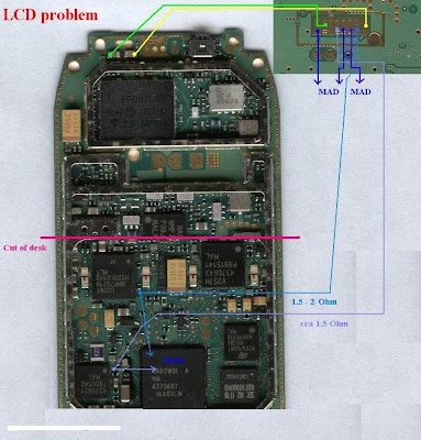
5310 Display Problem 5310 Display lcd Problem 5310 Lcd Display Problem 5310 Lcd Display Ways 5310 Blank Display 5310 Lcd Connector Jumper 5310 Lcd Connector Ways

5310 Display Problem


5310 Display lcd Problem
5310 Lcd Display Problem
5310 Lcd Display Ways
5310 Blank Display
5310 Lcd Connector Jumper
5310 Lcd Connector Ways

Nokia 6060 Local Mode, Nokia 6060 Test Mode, Nokia 6060 Local Mode Problem, Nokia 6060 Test Mode Problem, Nokia 6060 Local Mode Solution, Nokia 6060 Test Mode Solution,

Nokia 6060 Local Mode,
Nokia 6060 Test Mode,
Nokia 6060 Local Mode Problem,
Nokia 6060 Test Mode Problem,
Nokia 6060 Local Mode Solution,
Nokia 6060 Test Mode Solution.

6060 Charging solutions 6060 Charging Problem 6060 Charging Ways 6060 Charging 100% Workig Solution 6060 Not charging solutions 6060 Not charging Problem


6060 Charging solutions
6060 Charging Problem
6060 Charging Ways
6060 Charging 100% Workig Solution
6060 Not charging solutions
6060 Not charging Problem<

Nokia 6070 Network Problem, Nokia 6070 Antenna Switch jumpers, Nokia 6070 No Network, Nokia 6070 Low Network, Nokia 6070 Signal Problem, Nokia 6070 Antenna Swtich Ways, Nokia 6070 Network Solutions, Nokia 6070

Nokia 6070 Network Problem,
Nokia 6070 Antenna Switch jumpers,
Nokia 6070 No Network,
Nokia 6070 Low Network,
Nokia 6070 Signal Problem,
Nokia 6070 Antenna Swtich Ways,
Nokia 6070 Network Solutions,
Nokia 6070

6030 Display Problem,2626 Display Problem,2610 Display Problem 6030 Display lcd Problem 6030 Lcd Display Problem 6030 Lcd Display Ways 6030 Blank Display 6030 Lcd Connector Jumper 6030 Lcd Connector Ways 2626 Display lcd Problem 2626 Lcd Display Problem 2626 Lcd Display Ways 2626 Blank Display 2626 Lcd Connector Jumper 2626 Lcd Connector Ways 2610 Display lcd Problem 2610 Lcd Display Problem 2610 Lcd Display Ways 2610 Blank Display 2610 Lcd Connector Jumper 2610 Lcd Connector Ways

6030 Display Problem,2626 Display Problem,2610 Display Problem

6030 Display lcd Problem
6030 Lcd Display Problem
6030 Lcd Display Ways
6030 Blank Display
6030 Lcd Connector Jumper
6030 Lcd Connector Ways
2626 Display lcd Problem
2626 Lcd Display Problem
2626 Lcd Display Ways
2626 Blank Display
2626 Lcd Connector Jumper
2626 Lcd Connector Ways
2610 Display lcd Problem
2610 Lcd Display Problem
2610 Lcd Display Ways
2610 Blank Display
2610 Lcd Connector Jumper
2610 Lcd Connector Ways

Saturday, July 28, 2012

Inspiron N5030 Display change,


Display Assembly


Removing the Display Assembly

  1. Follow the instructions in Before You Begin.

  2. Remove the battery (see Removing the Battery).

  3. Remove the keyboard (see Removing the Keyboard).

  4. Remove the two screws that secure the display assembly to the base of the computer.

  1. Remove the palm rest (see Removing the Palm Rest). 

  2. Turn the computer over and open the display as far as possible.

  3. Make a note of the Wireless Mini-Card antenna cable routing and disconnect the Wireless Mini-Card antenna cable from the Wireless Mini- Card.

  4. Disconnect the display cable from the connector on the system board and remove it from the routing guide.

  5. Remove the two screws (one on each side) that secure the display assembly to the computer base.

  6. Lift and remove the display assembly out of the computer base.


1display assembly2screws (2)
3display cable4Mini-Card antenna cable


Replacing the Display Assembly

  1. Follow the instructions in Before You Begin.

  2. Place the display assembly in position and replace the two screws (one on each side) that secure the display assembly to the computer base.

  3. Route the display cable into the routing guide and connect the display cable to the connector on the system board.

  4. Route the Mini-Card antenna cable into the routing guide and connect the Mini-Card antenna cable to the connector on the Mini-Card.

  5. Turn the computer over and replace the two screws at the base of the computer.

  6. Replace the palm rest (see Replacing the Palm Rest).

  7. Replace the keyboard (see Replacing the Keyboard).

  8. Replace the battery (see Replacing the Battery).

CAUTION: Before turning on the computer, replace all screws and ensure that no stray screws remain inside the computer. Failure to do so may result in damage to the computer.

Display Bezel


Removing the Display Bezel


CAUTION: The display bezel is extremely fragile. Be careful when removing it to prevent damaging the bezel.
  1. Follow the instructions in Before You Begin.

  2. Remove the display assembly (see Removing the Display Assembly).

  3. Using your fingertips, carefully pry up the inside edge of the display bezel.

  4. Remove the display bezel.


1display bezel


Replacing the Display Bezel

  1. Follow the instructions in Before You Begin.

  2. Align the display bezel over the display panel, and gently snap it into place.

  3. Replace the display assembly (see Replacing the Display Assembly).

Display Panel


Removing the Display Panel

  1. Follow the instructions in Before You Begin.

  2. Remove the display assembly (see Removing the Display Assembly).

  3. Remove the display bezel (see Removing the Display Bezel).

  4. Disconnect the camera cable from the connector on the camera module.

  5. Remove the eight screws that secure the display panel to the display cover.


1display cable2screws (8)
3display panel4camera cable connector

  1. Lift the display panel off the display cover.

  2. Turn the display panel over and place it on a clean surface.

  3. Lift the tape that secures the display cable to the display board connector and disconnect the display cable.

  4. Peel off the camera cable from the back of the display panel.


1tape2display board connector
3display cable4back of the display panel

  1. Remove the four screws (two on each side) that secure the display panel brackets to the display panel.


1display panel brackets (2)2screws (4)


Replacing the Display Panel

  1. Follow the instructions in Before You Begin.

  2. Replace the four screws (two on each side) that secure the display panel brackets to the display panel.

  3. Connect the display cable to the display board connector and secure it with the tape.

  4. Adhere the camera cable to the back of the display panel.

  5. Place the display panel on the display cover and connect the camera cable to the connector on the camera module.

  6. Align the screw holes on the display panel with the screw holes on the display cover.

  7. Replace the eight screws that secure the display panel to the display cover.

  8. Replace the display bezel (see Replacing the Display Bezel).

  9. Replace the display assembly (see Replacing the Display Assembly). 

Monday, July 23, 2012

Nokia 3220 Solution


Nokia 3220 Solution


Nokia 3220 Solution Download pack


NOKIA 3310 LCD/SIM way


NOKIA 3310 LCD/SIM way


3310 LCD way

3310 SIM way


Nokia N91 Solution


Nokia N91 Solution


Nokia N91 Solution Download one pack

Nokia 6280 Solution pack


Nokia 6280 Solution pack


Nokia 6280 Download Solution One pack


Nokia 3250 Solution pack


Nokia 3250 Solution pack


Nokia 3250 Download Solution One pack

Nokia N70/N72 Solution Pack


Nokia N70/N72 Solution Pack


Nokia N70/N72 Download Solution One Pack

Nokia 5500 Solution


Nokia 5500 Solution


Nokia 5500 Solution Download pack

Nokia N80 Solution


Nokia N80 Solution


Nokia N80 Solution Download One Pack

Nokia 6280 Solution pack


Nokia 6280 Solution pack


Nokia 6280 Download Solution One pack

Nokia 3110c Solution


Nokia 3110c Solution


Nokia 3110c Solution Download one pack


NOKIA 6020 LCD way


NOKIA 6020 LCD way

NOKIA 6020 LCD way


Nokia C3-00 Insert Sim Solution


Nokia C3-00 Insert Sim Solution

Nokia C3-00 Sim Ways

Nokia C3-00 No Sim

Nokia C3-00


Make This Nokia C3-00 Insert Sim Solution.

Here's the Printed Circuit Board Layout of Nokia C1-01. The PCB board components mounting were so very compact in design. Nokia C1-01 PCB board have similarity to nokia C1-02 but unlike nokia c1-01 have VGA camera built on it while on Nokia C1-02 which don't have. The Nokia C1-00 is different from nokia C1-01 which it was built with a dual SIM card slot on it.


Here's the Printed Circuit Board Layout of Nokia C1-01. The PCB board components mounting were so very compact in design. Nokia C1-01 PCB board have similarity to Nokia C1-02 but unlike Nokia c1-01 have VGA camera built on it while on Nokia C1-02 which don't have. The Nokia C1-00 is different from Nokia C1-01 which it was built with a dual SIM card slot on it.


Nokia C1-01 Printed Circuit Board (PCB Board Rear)

nokia c1 c2 PCB board

Nokia C1-01 Printed Circuit Board (PCB Board Front)
nokia C1 repair solution

Nokia C1-01 Earpiece Speaker problemno audio Sound


Nokia C1-01 Earpiece Speaker problem, no audio Sound


Here's the solution for Nokia C1-01 Earpiece Speaker problem that has no audio Sound can b heard on it during a call is made. If this problem there is a possibility the earpiece speaker is already busted or damaged due to audio signal overdrive. Some factors are of dirty or oxidation build up on the earpiece terminal contact pads.

This solution below shows which particular components needs to be check for hardware repair troubleshooting.


Nokia C1-01 Earpiece Speaker Solution
nokia c1 Earpiece jumper ways tracks
Hints for repair:
Check the earpiece speaker first by using a multimeter set to X1, you can hear a crackling sound when hitting the two terminal with the tester's probes.
Clean the earpiece terminal contact pads on the C1-01 PCB board.
If the earpiece speaker is working and the contact pads is already cleaned but still the problem still exist. You may used the solution above and check those highlighted components, it is composed of filter coils, an ESD protection resistors and bypass capacitors.

Nokia C1-01 microSD memory card not detected problemmemory card not detected


This solution below can be used to fix Nokia C1-01 microSD memory card not detected problem issues, this problem may possibly occurred if the device suffered wet or water damaged. If this happens the Nokia C1-01 will not been able to detect any microSD memory card that inserted to it and it shows on the display the "NO memory card is inserted or memory card not detected".

The solution below below shows the location of certain component that needs to be check or replace to solve nokia C1-01 memory card not detected issues.


Nokia C1-01 microSD Memory Card Not detected
nokia C1 MMC IC jumper ways
The Nokia C1-01 MMC IC is located and mounted just besides the microSD slot. By replacing the MMC IC will possibly fix a damaged Nokia C1-01 that does not accept or read any microSD memory card.

Nokia C1-01 microphone problem


If encountered to fix a Nokia C1-01 microphone problem, here's the solution that might possibly solved the problem. The Solution below shows the microphone module on the Nokia C1-01 PCB board that needs to check or replace if found damaged. 

The MIC module is located and mounted at the bottom of the PCB board layout. near the antenna terminal contact pins.There are four components being mounted near to it and this are composed of filter coils and an ESD protection resistor or capacitors.


Nokia C1-01 MIC - microphone mouthpiece Solution
nokia C1 mic tracks jumper ways
You may check the filter coils first, if the coils is open or already busted replaced it.
If the filter coils were okay  you proceed to replace the MIC module if found damaged.


Nokia C1-01 LCD Display Problem Solution


This is the Nokia C1-01 Solution for an abnormal display problem, such as blank or empty screen, garbled or dark screen  display. This solution may works if you already tried installing a new LCD screen module and tried updating the device firmware but still the screen went wrong.

Refer to the solution below and do trace the LCD soldered pads connector down to the corresponding components such as the resistors and filter coils. The resistors has as resistance value of 22o ohms each. The VAUX is 2.8 volts and the VIO is 1.8 volts, you may also check these voltages.
This also includes the connection line paths of the LCD backlight LED, to fix if the white LED at the back of the LCD doesn't turns ON and shows a dark display.


Nokia C1-01 LCD Display Problem Solution

 Nokia C1-01 LCD Screen Display Problem Jumper Ways & Tracks

..........................................................................For More Information Continue Visit on http://gsmworldfree.blogspot.com/ More Use full Information Coming Soon. Wait For More New Information.And Post Your Comments In All Post.Email:ajcellpoint@gmail.com Continue>>>>>>>>>>>>>>>>>>>>>>>>>>>>>>>>>>>>>>>>>>>>>>>>

Here's the solution for Nokia C1-01 Not Charging problem like there is No Charging indication shows on the display when the battery charger is being plug-in. This problem is may caused by a faulty charger or a faulty components on nokia c1-01 PCB board. This problem may sometimes happens if the device suffered wet or water damaged or just exist. The solution below will show us the location of the particular components that needs to be check or by then replace if found damaged. Nokia C1-01 Not Charging Solution-Charger No response Repair Hints For C1-01 Not Charging: Check the charging pin connector, ensure that it is clean free from oxidation build up and the terminals were not bended and misaligned. Clean also the charging pin contact pads on the PCB board. Check the fuse if it is open or already blown out. A damaged fuse indicates that there is a shorted circuit or components happens on the PCB board. Check the chip diode if shorted, and then replace it.


Here's the solution for Nokia C1-01 Not Charging problem like there is No Charging indication shows on the display when the battery charger is being plug-in.
This problem is may caused by a faulty charger or a faulty components on nokia c1-01 PCB board. This problem may sometimes happens if the device suffered wet or water damaged or just exist.

The solution below will show us the location of the particular components that needs to be check or by then replace if found damaged.


Nokia C1-01 Not Charging Solution-Charger No response
nokia C1 charging jumper ways tracks

Repair Hints For C1-01 Not Charging:
Check the charging pin connector, ensure that it is clean free from oxidation build up and the terminals were not bended and misaligned.
Clean also the charging pin contact pads on the PCB board.
Check the fuse if it is open or already blown out. A damaged fuse indicates that there is a shorted circuit or components happens on the PCB board. Check the chip diode if shorted, and then replace it.

FIND ME ON FACE BOOK

YOU MAY LIKE THIS BLOG

VISITORS

Lebels

Recent Posts

Design by araba-cı | MoneyGenerator Blogger Template by GosuBlogger